Boards: the store and your own collections
Most projects are built on boards someone else designed: an ESP32 devkit, an
STM32 Nucleo, a Raspberry Pi, a Jetson. archec comes with a store of known
boards (arche-hw-store), and you can keep your own boards in collections
of the same shape. A board model says what the board is, which processors are
on it, and which connectors it has, with the pins they are wired to.
Using a board#
archec board listarche-hw-store 0.1.0 built in
beaglebone-black BeagleBone Black — AM3358 (linux, Cortex-A8) · I2C, SPI, GPIO, ANALOG
esp32-c3-devkitm-1 ESP32-C3-DevKitM-1 — ESP32-C3 (esp32, RISC-V RV32IMC) · CAN, UART, USB, RF
esp32-devkitc ESP32-DevKitC — ESP32 (esp32, Xtensa LX6) · CAN, UART, USB, RF
...It lists the store, then your collections. archec board show gives the
details of one board:
archec board show nucleo-g474reNUCLEO-G474RE (arche-hw-store 0.1.0, built in)
STMicroelectronics · NUCLEO-G474RE
https://www.st.com/en/evaluation-tools/nucleo-g474re.html
...
processors:
mcu STM32G474RE 1× Cortex-M4F · 170MHz · 128KiB · hal stm32 · chip "stm32g474re" · os bare-metal
mcu Renode: none — Renode 1.17 has no STM32G4 platform (its STM32_FDCAN model serves the STM32L552 only)
connectors:
can0 can FDCAN1, CAN FD (add a transceiver) [tx PA12, rx PA11]
uart2 uart USART2 (ST-LINK virtual COM) [tx PA2, rx PA3]
usb usb ST-LINK USB
pwr power 5 V USBarchec board add puts the board in your model:
archec board add main.arche nucleo-g474re --as ctl + uses arche-hw-store "^0.1"
+ include "arche-hw-store/boards/nucleo-g474re/nucleo-g474re.arche"
+ system RoverHw { part ctl: NucleoG474RE }
✓ nucleo-g474re is in the project — main.archeIt writes three things. It keeps them only if the project still builds as well as before.
project Rover {
  uses arche-hw-store "^0.1"               // the store, built into archec
}
include "arche-hw-store/boards/nucleo-g474re/nucleo-g474re.arche"

system RoverHw "Hardware" {                // the deployment's platform, or this one
  part ctl: NucleoG474RE
}
The options:
--asnames the part.--into <System>picks the system to add it to.--copycopies the board's folder intocomponents/instead, so that you can change it.
Running code on the board#
A binary placed on the board runs on the board's processor. Some boards have
more than one processor; the Kria KR260, for example, has apu and rpu.
archec then asks which one.
deployment D {
  system Rover
  platform RoverHw
  binary fw on ctl { thread t { runs controller } }      // ctl.mcu, the STM32G474RE
  route controller.bus -> motor.bus over can_bus { id 0x120 }
}
The platform links the bus to the board's connector (ctl.can0 -> can_bus).
Then archec gen --target embassy drives the CAN controller on the board's
pins, not on its defaults. Here that is FDCAN1 on PA11/PA12. On the nRF52840
DK it would be an MCP2515 on the Arduino header (P1_15, P1_13, P1_14, CS
P1_12, INT P1_03).
What a board is#
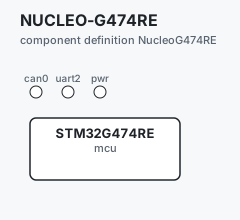
/// ST NUCLEO-G474RE: an STM32G474RE (Cortex-M4F with FDCAN) on a Nucleo-64.
component NucleoG474RE "NUCLEO-G474RE" {
  kind board
  description "One 170 MHz Cortex-M4F, 128 KB SRAM, three FDCAN controllers…"
  product { vendor "STMicroelectronics"; part-number "NUCLEO-G474RE"; url "https://…" }
  component mcu "STM32G474RE" {
    kind processor
    compute { cores 1; core-type "Cortex-M4F"; hal stm32; chip "stm32g474re"; freq 170MHz; ram 128KiB; os bare-metal }
  }
  inout can0:  can "FDCAN1, CAN FD (add a transceiver)" { pins { tx PA12; rx PA11 } }
  inout uart2: uart "USART2 (ST-LINK virtual COM)" { pins { tx PA2; rx PA3 } }
  in pwr:      power "5 V USB"
}
kind boardis built in, likeprocessorandbus.product { vendor; part-number; url }is what you would order.- A processor says what code is built for it:
- bare metal:
halandchip, which name what the Embassy crate builds for; - Linux:
os, for a host crate.
- bare metal:
pins { role pin; … }on a connector names the chip's pins. They are written as the HAL crate writes them:GPIO4(esp32),PA11(stm32),PIN_16(rp),P1_15(nrf). A role says what a pin does. The roles archec reads are:txandrx, for a CAN controller;sck,mosi,miso,csandint, for an SPI one (the MCP2515);sdaandscl.
A board folder is a component folder. It uses only what it declares, the built-in port types and the standard library. So it works where it is, and as a copy.
What a board has#
Each board of the store also lists everything a project can use on it. It is
written at the end of the board's file, between two marker lines, by
tools/board-resources (see "Where the data comes from" below):
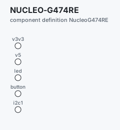
component NucleoG474RE "NUCLEO-G474RE" {
  // … the board as above, with `flash 512KiB` in its compute …
  // the power it gives to what you wire to it
  out v3v3:   power "3.3 V (Arduino power header)" { voltage 3.3V }
  out v5:     power "5 V (Arduino power header)" { voltage 5V }
  // on the board itself
  out led:    gpio "User LD2, green" { pins { io PA5 } }
  in button:  gpio "User button (low when pressed)" { pins { io PC13 } }
  // buses ready to use, on the pins Zephyr's board puts them
  inout i2c1: i2c "I2C1 (Arduino D14, D15)" { pins { sda PB9; scl PB8 } }
  // how many of each peripheral
  peripherals {
    uart [LPUART1, UART4, UART5, USART1, USART2, USART3]
    i2c [I2C1, I2C2, I2C3, I2C4]
    adc { ADC1 { channels 14; bits 12 }; ADC2 { channels 16; bits 12 } }
    pwm { TIM1 4; TIM2 4; TIM15 2 }
  }
  // what each pin can be, besides a GPIO
  pinout {
    PA9 [ADC5_IN2, I2C2_SCL, TIM1_CH2, TIM2_CH3, USART1_TX]
    PB8 [FDCAN1_RX, I2C1_SCL, TIM4_CH3, TIM16_CH1, TIM8_CH2, USART3_RX]
  }
}
flash(incompute) is the program memory of a microcontroller.- The rails are
outports of typepower.voltageis what they give.currentis the most they give, when the board's guide says it: the Pico's 3V3(OUT) gives 300 mA. - The on-board items are ports too:
led,button, the C3'srgb_led.pins { io PA5 }is one line: a LED, a button, a PWM output, an analog input. - The buses ready to use are the UART, I²C and SPI buses the board's Zephyr
devicetree enables, on its pins. Link a sensor to one:
ctl.i2c1 -> env.i2c. Like every connector, they are alternatives until a system links them. peripheralscounts each kind:uart,i2c,spi,can(their names),adc(each one's channels and bits),dacandpwm(each one's channels),usb,ethernet,radio.any-pin [uart, i2c]: on an ESP32 or an nRF52840, these peripherals go on any pin.shared [[I2C0, SPI0]]: one peripheral under two names (on the nRF52840, I2C0 and SPI0 are the same hardware).
pinoutsays what each pin can be, as the chip names its functions:USART1_TX,I2C1_SDA,SPI1_SCK,FDCAN1_TX,TIM1_CH2(a timer's channel: PWM),ADC1_IN5,DAC1_OUT1. On a Linux board, the keys are the header pins' ports, and the names are Linux's:pin3 [GPIO2, I2C1_SDA](/dev/i2c-1).io-level 3.3Vis the level of the board's pins. A port that says its ownpins { level … }keeps it.
archec board show <board> prints all of it: the peripherals, the rails, and
each pin with what it can be and which of the board's connectors take it.
Where the data comes from#
node tools/board-resources/fetch.mjs      # once: Zephyr's files, at pinned revisions
node tools/board-resources/generate.mjs # writes the blocks; --check says what would change- Microcontroller boards (the Nucleos, the Picos, the nRF52840 DK, the ESP32 boards): from Zephyr v4.2.0's devicetree (Apache-2.0) and hal_stm32 at the revision Zephyr pins. The STM32 pin functions are hal_stm32's pinctrl tables for the board's exact package. The RP2040's are Zephyr's pinctrl header. Flash sizes, ADC resolutions, LEDs, buttons, the buses and the Arduino header names are the board's devicetree.
- What the devicetree does not say comes from the chips' datasheets and the
boards' user guides, in
tools/board-resources/chips.mjs: the ESP32 and nRF52840 analog pins (their other peripherals go on any pin), the pins each board brings out, the rails. - Linux boards: the Raspberry Pi 4 and 5, the Jetson Nano, the BeagleBone Black and the PocketBeagle have their header's I²C, SPI, UART, PWM and analog pins, from their documentation. The other Linux boards have only their PWM pins (from their Go driver, adapted from Gobot), their rails and their level.
- A value that is not sure is left out: a wrong pin is worse than a missing
one. Each table in
chips.mjssays where it comes from.
The checks#
archec check, archec pins and the editor compare a system with its boards.
Each check has archec explain <code>:
pin-function: a pin cannot be what the port uses it for. I²C SDA on a pin with no SDA, a servo (a port labelled "PWM") on a pin with no timer, a potentiometer (ananalogport) on a pin with no ADC. The message lists the pins that can.pin-conflict: one pin used twice. Besides two ports on one pin, a Linux header pin's port and the bus on that pin (pi.pin3andpi.i2c1), and a one-pin port linked to two parts.board-peripheral:- two ports on one peripheral: two I²C ports both on I2C1, two servos on
pin12andpin32of a Raspberry Pi 4 (both are PWM0: they would move together); - more of a kind than the board has: a 2nd I²C on an ESP32-C3, a 3rd PWM output on a board with 2.
- two ports on one peripheral: two I²C ports both on I2C1, two servos on
board-supply: a part powered from a rail whose voltage it does not take. The part's power port says what it takes:in pwr: power { voltage 1.71V..3.6V }. The quick fix links it to the board's rail that fits.board-current: the parts on a rail draw more than it gives. Each part's power port says what it draws (current 15mA), or itspoweris divided by the rail's voltage.pin-level: the board'sio-levelis its ports' level. A 5 V echo (pins { level 5V }, the HC-SR04's) on a 3.3 V pin is a warning.
Some devices of the store say what they take: the BME280, BMP180/280, MPU-6050,
ADXL345, HMC5883L, BH1750, SHT3x, ADS1x15, PCA9685, MCP3008, DS18B20 and the
HC-SR04. The values are the chip's, from its datasheet. A module with a
regulator on it may take 5 V: give the part your own voltage if so.
Pictures#
archec board picture nucleo-g474re -o nucleo.svg      # one board
archec board picture main.arche -o hardware.svg       # each system that has boards
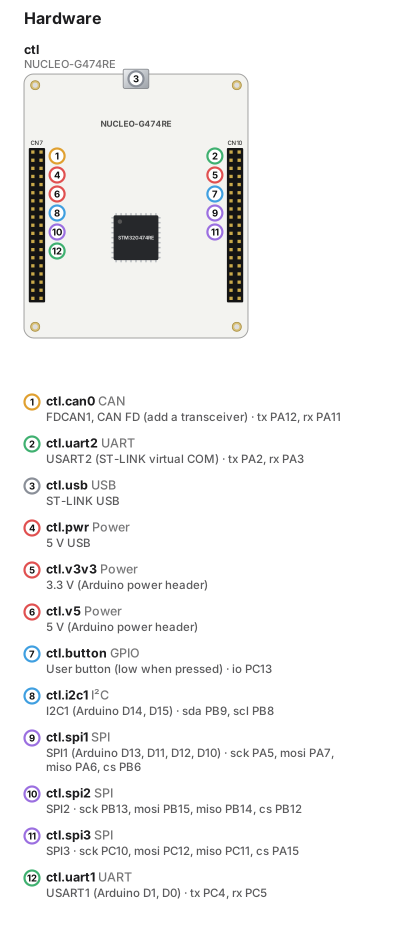
archec draws a board's picture from its model. The picture shows:
- the board's outline and colour;
- its processor;
- its pin headers and connectors;
- a number on each port, with a legend that says what the port is and which pins it uses.
On a Raspberry Pi, the numbers point at the header pins that a bus is on (I2C1 on pins 3 and 5).
For a model, archec board picture draws each system's boards, devices and
buses, with the wires its links make: a board on a CAN bus, a sensor on the
Pi's I2C. --system picks one system. The playground's Hardware diagrams
are these pictures. An example is examples/can-bench: a Raspberry Pi, a
Nucleo and an ESP32 on one CAN bus, and a BME280 sensor.
These are drawings, not photos. archec knows how each store board looks: its size, its colour, where its connectors are. A board of your own is drawn from a guess: a small dark board with headers, or a single-board computer if it runs Linux.
Pin planning#
archec pins main.archeFor each board, it prints each pin: the port and the role on it, where the
port is linked, and whether the part wrote the pin. Right after
archec board add, nothing is linked yet:
RoverHw.ctl — NUCLEO-G474RE · STM32G474RE (stm32)
  PA2   uart2 tx  (not linked)
  PA3   uart2 rx  (not linked)
  PA11  can0 rx   (not linked)
  PA12  can0 tx   (not linked)
In a model with links, and with a part that sets its own pin
(part ctl: NucleoG474RE { inout can0 { pins { tx PA2 } } }, over the board's
PA12), it looks like this:
Hw.ctl — NUCLEO-G474RE · STM32G474RE (stm32)
  PA2   can0 tx   -> can_bus  (the part's)
  PA2   uart2 tx  -> esp.uart0
  PA3   uart2 rx  -> esp.uart0
  PA11  can0 rx   -> can_bus
After the pins come the pin plan's warnings. archec check and the editor give
them too:
pin-conflict: one pin is used by two ports of a board, or by two roles of one port.- Only the ports the system links, or whose pins a part writes, count. Until then, a board's connectors are alternatives: the Pico's SPI0 and its MCP2515 share pins.
- A component that
extendsa board is told when a pin it writes is one of its board's connectors' pins.
pin-function: the chip cannot use the pin in this way.- On the RP2040: UART TX only on GPIO 0, 4, 8…, and RX on 1, 5, 9…; I2C SDA on even pins; SPI SCK, MOSI and MISO on their own pins. One port's pins must be on one peripheral: TX on UART1 with RX on UART0 is wrong.
- On the ESP32: GPIO34–39 are inputs only. The pins wired to the module's flash are taken: GPIO6–11, 12–17 on the C3, 26–32 on the S3.
- On every board of the store, against its
pinout("What a board has").
pin-pair: the two ends of a link do not pair.txmust meet the other end'srx. SCK, MOSI, MISO, SDA and SCL meet the same role.- A CAN controller on a bus needs both
txandrx.
pin-level: a link between ports whose voltage levels differ. For example,pins { tx PIN_0; rx PIN_1; level 3.3V }on one side andlevel 5Von the other.levelis not a pin. A board'sio-levelis its ports' level. The Nucleo boards say none: most STM32 pins take 5 V (FT pins), and archec does not know which.
Zephyr devicetree#
archec gen main.arche --target devicetree -o generatedThis writes a devicetree overlay for each binary of the deployment that runs on
a board's microcontroller. The overlay is named as west (Zephyr's build tool)
names the board, for example
generated/devicetree/steer_fw/boards/nucleo_g474re.overlay. Copy its
boards/ folder into the Zephyr application.
The overlay has a node for each CAN, UART, I2C and SPI connector of the board
that the platform links (steer_mcu.can0 -> chassis_can):
/ {
	aliases {
		arche-chassis-can = &fdcan1;
	};
	chosen {
		zephyr,canbus = &fdcan1;
	};
};

/* steer_mcu.can0 — FDCAN1, CAN FD (add a transceiver): tx PA12, rx PA11 */
&fdcan1 {
	status = "okay";
	pinctrl-0 = <&fdcan1_tx_pa12 &fdcan1_rx_pa11>;
	pinctrl-names = "default";
	bitrate = <500000>;
};- Pins. They are the port's pins: a part's own
pinswin over the board's. Each is named as its HAL names it: hal_stm32's pinctrl nodes,NRF_PSEL(…)groups, the RP2040 and ESP32 pinmux macros. - Peripheral. It is the one the connector's name says (
USART2,FDCAN1,TWAI0). On the RP2040, it is the one its pins belong to. - Speed. It is the link's
bitrate, else the bus's:bitratefor CAN (1 Mbit/s at most; a CAN FD bus addsbitrate-data);current-speedfor a UART;clock-frequencyfor I2C.
- CAN on SPI. The MCP2515 of the nRF52840 DK and of the Pico is an
mcp2515node under the SPI, with its CS and INT as GPIOs. - I2C devices. A device linked to the board is a node at its
address. You add itscompatible. - Aliases. Each bus has an alias,
arche-<bus>. Under Zephyr (__ZEPHYR__), thedrivers.cofarchec gen --target csends the frames of a CAN or UART bus onDEVICE_DT_GET(DT_ALIAS(arche_<bus>)). Itsmain.creturns, and leaves the threads running. The C's platform layer isarche_rt_posix.c, on Zephyr's POSIX API (CONFIG_POSIX_API). That setting is in theprj.confwritten once beside the overlay.
KiCad netlist#
archec kicad main.arche [CarHw] -o car.netThis writes the wiring of a system as a KiCad netlist. The system is the one you name, else the deployment's platform. pcbnew reads the netlist (File → Import → Netlist), and eeschema can compare it with a schematic.
Symbols. Each part whose ports carry signals is a symbol with no footprint. A board is
A1,A2…; anything else isU1…. What is on a board belongs to the board's symbol.Pins of a symbol. They are its ports' signals, taken from the first of these that exists:
- the board's pins, by role (
uart2.TX/PA2); - the port type's
wires (wire canh "CAN_H"); - the usual signals of a built-in type: CAN_H/CAN_L, TX/RX, SDA/SCL, SCK/MOSI/MISO/CS, V+/GND.
A part that sets its own pins (
part pico: RaspberryPiPico { inout i2c0 { pins { … } } }) gets a symbol of its own.- the board's pins, by role (
Nets. A link is one net per signal.
- TX and RX cross. The net is named after the TX end (
pico_uart0_TX). - SDA goes to SDA.
- Everything linked to a
kind buscomponent shares its nets (chassis_can_CAN_H). Two TX/RX ends on one bus cross. - Every GND is one net.
- TX and RX cross. The net is named after the TX end (
CAN. A CAN connector with controller pins (
tx/rx, or an MCP2515's SPI) puts CAN_H/CAN_L on the bus side. A note says that the transceiver goes between them.
Your own collection#
archec board new carrier-v2 --in ~/arche-boards --from nucleo-g474re --name "Carrier v2"
archec board check ~/arche-boards
archec board extract main.arche RoverHw.ctl --in ~/arche-boards   # a board the model defines
A collection is a library: a folder with a library.arche (board new makes
it) and boards/<id>/<id>.arche. The pictures go in boards/<id>/assets/.
- A project sees a collection through
libraries "<folder>".board addwrites that line. - Every project on the machine sees the collections listed in
ARCHE_BOARDS(a path list). The VS Code settingarche.boardCollectionssets it for the editor and its language server. arche.lockrecords the collection's version and fingerprint, as for any library.
board check builds each board on its own, and checks three things:
- its processors say
halandchip, oros; - its pins are pins of its chip;
- its picture is there.
In VS Code#
The Store Shelves view of the Arche side bar (it was the Boards view) lists the boards the model uses (click one to go to the part), then the six shelves. Its Boards shelf has the store and your collections, and its Sensors and actuators shelf the devices, by what they do.
- On a board: Add to Model… (from the collection or as a copy, and into which system), Show Board Details (its card, processors, connectors, pins), Open Definition, Duplicate to My Collection….
- On a collection: New Board…, Check Board Collection (results in the Problems view), Reveal Collection Folder.
- On a device: Add Device to Model… (its name, and which bus of the model's boards it goes on), Show Card.
- In the title bar: add, filter every shelf (by name, what it does, vendor, chip, HAL, core), refresh, New Board…, Add Board Collection….
- On a component of the Model view: Save as Board in My Collection….
- Drag a board from the view into a
.archeeditor. archec writespart esp32_c3_devkitm_1: Esp32C3DevKitM1where you drop it, with the part's name selected so that you can change it.- Dropped outside any block, the part goes in a new
system <Project>Hw "Hardware". - The board's
includeand the project'susesare written asboard addwrites them. - Dropped in another kind of editor, it is the
partline as text.
- Dropped outside any block, the part goes in a new
The editor knows the boards too.
Completion.
- After
part x:(andextends), it offers the boards of the store and of your collections, with vendor and part number. If you choose one the model does not include yet, it also writes itsinclude. In the file that has the project block, it writesuses arche-hw-store "^0.1", orlibrariesandusesfor a collection of yours. - In
pins { … }on a port, it first offers the roles. Each comes with the pin the board gives it on a port of that type (tx PA12). - After a role, it offers the board's pins with what they are wired to
(
PA11 — can0 rx, FDCAN1). The pin of the same role and port type comes first. - In a part of a board (
part ctl: NucleoG474RE { … }, or a component thatextendsone), it offers the board's connectors with their type, name and pins. Choosing one writes it with its pins, for you to change:inout uart2 { pins { tx PA2; rx PA3 } }.
- After
Hover.
- On a board's name, or on a part of one: its vendor, part number and URL;
its processors (core, clock, RAM,
halandchip); its connectors with their pins; and the collection it comes from. - On a pin in
pins { … }: the chip it is on, and what the board wires to it (PA11 — can0 rx, FDCAN1). - On a role: what it is for.
- On a board's name, or on a part of one: its vendor, part number and URL;
its processors (core, clock, RAM,
Warnings (
board-pin, also inarchec check). A pin name that the board's chip does not use is a warning. This applies on a board, on a part of one, and on a component that extends one. The quick fix offers the nearest pin, and the pins the board's connectors use:NUCLEO-G474RE has no pin 'PB99': its STM32G474RE (stm32) names them like PA11. Did you mean 'PB9'?A role archec does not read (
tz) is a warning too.
The store#
| Board | Processor | Builds for | CAN |
|---|---|---|---|
| ESP32-C3-DevKitM-1 | ESP32-C3, RISC-V | hal esp32, esp32c3 |
TWAI on GPIO2/GPIO3 |
| ESP32-S3-DevKitC-1 | ESP32-S3, 2× Xtensa LX7 | hal esp32, esp32s3 |
TWAI on GPIO4/GPIO5 |
| ESP32-DevKitC | ESP32, 2× Xtensa LX6 | hal esp32, esp32 |
TWAI on GPIO21/GPIO22 |
| NUCLEO-G474RE | STM32G474RE, Cortex-M4F | hal stm32, stm32g474re |
FDCAN1 on PA12/PA11 |
| NUCLEO-F446RE | STM32F446RE, Cortex-M4F | hal stm32, stm32f446re |
CAN1 on PA12/PA11 |
| NUCLEO-H743ZI2 | STM32H743ZI, Cortex-M7 | hal stm32, stm32h743zi |
FDCAN1 on PD1/PD0 |
| Raspberry Pi Pico, Pico W | RP2040, 2× Cortex-M0+ | hal rp, rp2040 |
MCP2515 on SPI0 |
| nRF52840 DK | nRF52840, Cortex-M4F | hal nrf, nrf52840 |
MCP2515 on the Arduino header |
| Raspberry Pi 4, Pi 5 | BCM2711 / BCM2712 | Linux (std) | an MCP2515 HAT, SocketCAN |
| Jetson Orin Nano Developer Kit | 6× Cortex-A78AE | Linux (std) | — |
| Kria KR260 | K26: 4× Cortex-A53, 2× Cortex-R5F, PL | Linux (apu), FreeRTOS (rpu) |
— |
| Raspberry Pi 4 and 5 (Go driver) | BCM2711 / BCM2712 | Linux (Go: raspi.NewAdaptor) |
— |
| Jetson Nano Developer Kit | Tegra X1, 4× Cortex-A57 | Linux (Go: jetson.NewAdaptor) |
— |
| BeagleBone Black, PocketBeagle | AM3358, Cortex-A8 | Linux (Go: beaglebone, pocketbeagle) |
— |
| ASUS Tinker Board, Tinker Board 2 | RK3288 / RK3399 | Linux (Go) | — |
| FriendlyELEC NanoPi NEO, NanoPC-T6 | Allwinner H3 / RK3588 | Linux (Go) | — |
| Orange Pi 5 Pro | RK3588S | Linux (Go) | — |
| PINE64 ROCK64, Radxa ROCK Pi 4, Radxa Zero | RK3328 / RK3399 / S905Y2 | Linux (Go) | — |
None of these boards has a CAN transceiver. Wire one between the pins and the bus.
In Renode#
Renode (1.17) is an emulator of microcontrollers.
archec gen main.arche --target renode --deployment D runs a deployment's
microcontrollers in it, without the boards. It makes:
- a machine for each processor that has a binary, with Renode's own description of its chip, and the binary's ELF loaded;
- a
CANHubfor each CAN bus of the platform; - a
UARTHubfor each UART link of the platform; - the board's devices that Renode models, where the firmware drives them: a BME280 at its I²C address, a relay or an LED on its pin;
- the UART to the computer (the ST-LINK's virtual COM port) recorded to
<binary>.trace, whicharchec timingandarchec replayread.
archec board show says, for each processor, what Renode runs it as
(Renode: …).
| Chip (boards) | Renode platform | CAN | Notes |
|---|---|---|---|
stm32h743zi (NUCLEO-H743ZI2) |
platforms/cpus/stm32h743.repl |
FDCAN1 (MCAN) | Renode's RCC does not keep FDCANSEL: the .resc makes it read back PLL1_Q, the clock the generated main.rs picks |
stm32f446re (NUCLEO-F446RE) |
platforms/cpus/stm32f4.repl |
CAN1 (bxCAN) | an STM32F407: more flash and RAM, the same CAN and USARTs at the same addresses. Its timers are set to 16 MHz, the clock the generated firmware keeps |
nrf52840 (nRF52840 DK) |
platforms/cpus/nrf52840.repl |
— | Renode has no MCP2515: the board's CAN is not on the bus |
stm32g474re (NUCLEO-G474RE) |
— | no STM32G4 in Renode | |
rp2040 (Pico, Pico W) |
— | no RP2040 in Renode | |
esp32, esp32c3, esp32s3 |
— | no Espressif chip in Renode | |
| Linux processors (Pi, Jetson, Kria's APU…) | — | not emulated: their binary runs on a host; the .resc has a SocketCAN bridge for it, commented (Linux hosts) |
A board's CAN or UART port is the Renode peripheral that its text names
("FDCAN1, CAN FD…", "USART2 (ST-LINK virtual COM)"). A CAN port that names
none is the first controller, the one the generated firmware drives. For a UART
that names none, archec says so, and does not guess.
archec gen main.arche --target embassy --deployment Bench -o out
archec gen main.arche --target renode --deployment Bench -o out
(cd out/embassy/brake_fw && cargo build --release)
renode out/renode/Bench/Bench.resc              # the machines, running
renode-test out/renode/Bench/Bench.robot        # the checks
The ELF paths are variables at the top of machines.resc ($brake_fw). Change
them for a firmware built elsewhere, or in C.
The Robot suite (Bench.robot) checks the following:
- each binary that talks on a bus has started its CAN controller;
- for each test case, what Renode can see:
- a
sendfrom a part that Renode does not run is put on the bus, encoded as the codec lays the message out. The firmware must read it. - an
expect sent("MSG")counts the frames the machines sent with that message's CAN id; do sensor.temperature = 31sets the device's reading in Renode, andexpect relay.closedreads the relay's pin.
- a
examples/car-bench is the car's actuator firmware, run this way.
examples/greenhouse runs a NUCLEO-F446RE with a BME280 and a relay:
./board.sh --renode builds it, runs it in Renode and measures it (see
the board tutorial).
Devices and their drivers#
The store also has devices: sensors, displays (below), motors,
LEDs, ADCs… There are 87 of them, one folder each under devices/. The Linux
boards above also have their driver in Go, under
boards/<board>/drivers/go/.
Both come from Gobot v2.6.0 (Apache-2.0, see
LICENSE-gobot and NOTICE). They are adapted so that they import nothing of
Gobot.
include "arche-hw-store/sensors.arche"

/// BME280 temperature, pressure and humidity sensor.
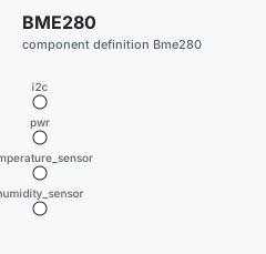
component Bme280 "BME280" {
  kind device
  product { vendor "Bosch Sensortec"; part-number "BME280"; driver "i2c.NewBME280Driver" }
  inout i2c:             i2c "I²C" { address 0x77 }
  in pwr:                power "supply (1.71V to 3.6V)" { voltage 1.71V..3.6V }
  in temperature_sensor: provides TemperatureSensor "Temperature" { noise 1°C; resolution 0.01°C }
  in humidity_sensor:    provides HumiditySensor "Humidity" { noise 3%RH; resolution 0.008%RH }
  fn temperature -> Temperature "Temperature (°C)"
  fn humidity -> Humidity "Humidity (%RH)"
}
Most devices also say what they do: a port that provides an interface of
sensors.arche (see Sensors by what they do), with
their accuracy and their supply.
drivernames the device's Go constructor indevices/go/<family>/. The families are i2c, spi, gpio, aio and onewire. On a board,drivernames its adaptor.addressis the device's I²C address. Two devices at the same address on one bus are an error (bus-address). A part can move one:part env2: Bme280 { inout i2c { address 0x76 } }.- A Linux board has a port for each header pin its driver knows (
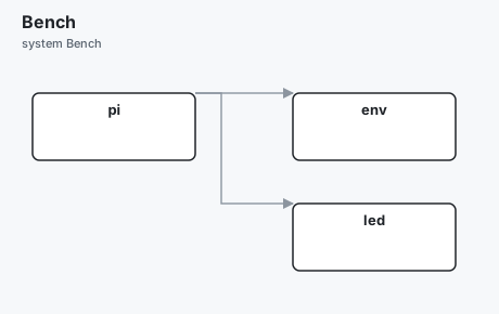
pin11, orp8_07on a BeagleBone). So you link a device's pin to the board's pin:
system Bench {
  part pi:  RaspberryPi4
  part env: Bme280
  part led: GpioLed
  pi.i2c1 -> env.i2c
  pi.pin11 -> led.pin
}
The Go code is in one module, archehw (lib/arche-hw-store/go.mod):
- the runtime, in
runtime/go/: Gobot's interfaces asarchert, and the Linux access for I²C, SPI, GPIO, PWM, analog and 1-Wire; - the device drivers, in
devices/go/; - the boards' drivers, beside each board.
It needs nothing outside Go. Gobot's own tests come with it: run go test ./...
in lib/arche-hw-store (npm test runs them too).
Two tools keep it in step with Gobot:
go run ./tools/gobot-port <gobot checkout> lib/arche-hw-store "v2.6.0 (798be8c)"   # the Go code
go run ./tools/gobot-catalog lib/arche-hw-store                                     # devices/ and the boards' .arche
Gobot's code does not have the vendors, part numbers, units and boards'
processors. They are in tools/gobot-catalog/known.go and known_boards.go.
What each device does, its accuracy and its supply are in
tools/gobot-catalog/sensors.go.
Sensors by what they do#
A model says what it needs, a temperature sensor, and only then which part
gives it. lib/arche-hw-store/sensors.arche has one interface for each thing
a sensor or an actuator does, its operations typed with the quantities of
arche-types:
| Measures | Interface | Gives |
|---|---|---|
| Temperature | TemperatureSensor |
temperature() -> Temperature (°C) |
| Humidity | HumiditySensor |
humidity() -> Humidity (%RH) |
| Air pressure | PressureSensor |
pressure() -> Pressure (Pa) |
| Acceleration, rotation | Accelerometer, Gyroscope, Imu (both) |
acceleration() -> Vec3 (m/s²), angular_velocity() -> Vec3 (rad/s) |
| Heading | Magnetometer |
heading() -> Angle (rad) |
| Distance | DistanceSensor |
distance() -> Distance (m) |
| Light | LightSensor |
illuminance() -> Illuminance (lx) |
| Air quality | AirQualitySensor |
eco2() -> Co2 (ppm), tvoc() -> Tvoc (ppb) |
| Current and voltage | CurrentSensor |
current() -> Current, voltage() -> Voltage |
| Position | GpsReceiver |
fix() -> GpsFix |
| Rotation angle | Encoder |
angle() -> Angle |
| A press, a motion | Button, MotionSensor |
pressed() -> bool, motion() -> bool |
| Does | Interface | Takes |
|---|---|---|
| Light | Led, RgbLed |
on(), off(), toggle(), state(); set_rgb(r, g, b) |
| Sound | Buzzer |
on(), off(), tone(frequency, duration) |
| Switch a load | Relay |
on(), off(), toggle(), state() |
| Move | Servo, DcMotor, Stepper |
move(angle); forward(speed), backward(speed), off(); move(steps) |
| Show text | Display |
clear(), write(text) |
A device gives one by a port named after it: the BME280 has
temperature_sensor, humidity_sensor and pressure_sensor. The controller
says what it needs with requires, and calls it in its body:
project Greenhouse {
  uses arche-hw-store "^0.1"
}
include "arche-hw-store/devices/bme280/bme280.arche"
include "arche-hw-store/devices/relay/relay.arche"

component Thermostat "Thermostat" {
  out air: requires TemperatureSensor
  out fan: requires Relay
  fn main ```arche
    while true {
      if air.temperature() > 28.0 {
        fan.on()
      } else {
        fan.off()
      }
      wait 1s
    }
  ```
}

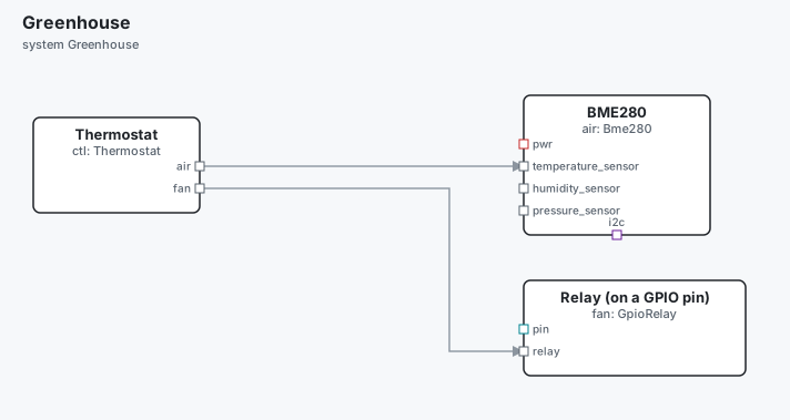
system Greenhouse {
  part air: Bme280
  part fan: GpioRelay
  part ctl: Thermostat
  ctl.air -> air.temperature_sensor
  ctl.fan -> fan.relay
}
To use a DS18B20 instead, change part air: Bme280 to part air: Ds18b20 and
its include. The link, the body, the simulation and the tests stay as they
are.
55 of the 87 devices are placed under these interfaces. The others stay by their bus:
- the ADCs (ADS1x15, MCP3xxx, PCF8591, YL-40) and the port expanders (MCP23017, PCA9501, PCA953x);
- the PWM and motor HATs (PCA9685, Adafruit 2327 and 2348);
- the RFID readers (MFRC522), the LED matrix drivers (MAX7219, AiP1640) and the APA102 strip;
- the haptic driver (DRV2605L), the clock (PCF8583), the Wii Nunchuck and the GrovePi;
- the generic and analog drivers, and the sound and vibration sensors.
Gobot's generic drivers had the names of the interfaces. They are now
GpioLed, GpioButton, GpioRelay, GpioBuzzer, GpioRgbLed, HobbyServo,
GpioStepper and Thermistor. Their folders (led, button…) did not change.
Accuracy and supply#
A device's port says how it reads: noise (the datasheet's accuracy, drawn as
a gaussian's σ in the simulator) and resolution (the step a reading is
rounded to). Its pwr port says its supply (voltage 1.71V..3.6V, and the
most it draws when the datasheet says it), and its hardware record, for a
distance sensor, its range (hardware {range: {min: 0.02m, max: 4m}}). These
come from the datasheets, only where we are sure of them; the rest is left out.
A fn the Go driver gives in another shape keeps a line above it: // Go: Distance() gives cm. In archec gen --target go, read the driver in user.go
and set the part's variables; the operations are the model's.
In the simulator#
A device with no code of its own does what its interface does, in archec sim,
its page and the playground (src/sensorsim.ts, written once per interface):
| Interface | In the simulator |
|---|---|
TemperatureSensor |
±0.5 °C about temperature (21 °C), over 10 minutes, plus the device's noise |
HumiditySensor, PressureSensor, LightSensor, AirQualitySensor, CurrentSensor, Magnetometer |
the same, about 45 %RH, 101325 Pa, 300 lx, 600 ppm and 50 ppb, 0.25 A at 5 V, 0.5 rad |
DistanceSensor |
something coming and going ±0.4 m about distance (1 m) every 20 s, within the device's range |
Accelerometer, Gyroscope |
gravity on z, still, with the noise on each axis |
GpsReceiver |
a 3D fix about latitude and longitude, 2.5 m of noise |
Button, MotionSensor, Encoder |
pressed, motion, angle, as a scenario sets them |
Led, Relay, Buzzer, RgbLed, Display |
their state (lit, closed, text…), each change said in the trace |
Servo |
angle turns toward target at 60° in 0.1 s, within 0..π |
DcMotor |
speed follows its command with a 0.2 s lag |
Stepper |
step moves toward target at rpm (60), 200 steps a turn |
The names in backquotes are variables the part gets in the simulator. A test case changes the world through them, with no plant:
test-plan TP "The greenhouse" {
  case TC-WARM "The air warms: the fan runs" {
    at 2s do air.temperature = 30
    at 3.5s expect fan.closed
  }
  case TC-DOOR "The door button" {
    at 2s do door.pressed = True
    at 3s expect ctl.held
  }
}
archec sim main.arche --testlib/arche-hw-store/tests/greenhouse.arche is such a model. Its cases count
on the devices' cards (archec shelf sensors bme280: "2 tests in the
simulator").
15 of the devices also have a Rust driver, for the microcontroller boards
(archec gen --target embassy): rust-driver in their product names the
crate it is built on. See drivers.md.
Displays#
Each screen in the store says what a ui on it can use. Its
hardware {display: {…}} record gives the size in pixels, the density, the
input and the controller.
| Device | Display | Input | Bus |
|---|---|---|---|
ili9341 |
2.8" 320×240, 143 dpi, RGB565 | touch (XPT2046) | SPI, DC, reset, backlight, touch IRQ |
st7789 |
2.0" 240×320, 200 dpi | keys | SPI, DC, reset, backlight |
st7789-240x240 |
1.3" 240×240, 261 dpi | keys | SPI, DC, reset, backlight |
ssd1306, spi-ssd1306 |
0.96" 128×64 mono, 149 dpi | keys | I²C 0x3C, SPI (Gobot's drivers) |
hdmi-display |
1920×1080, 92 dpi | pointer | HDMI, USB |
archec device list --displays
archec device add main.arche ili9341 --into RoverHw
A component with a ui { } and no display of its own takes the display part
beside it. archec looks for it first in a system the component is a part of,
then in the platform of a deployment of that system. archec ui then says
"from the hardware". The ui's own input wins over the display's.
A display of your own is a component with the same record:
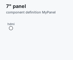
component MyPanel "7\" panel" {
  kind device
  hardware {display: {width: 1024, height: 600, dpi: 170, input: "touch"}}
  in hdmi: hdmi
}
archec gen --target ui-lvgl and ui-slint write the ui for it (see
ui). The SSD1306's record is in
tools/gobot-catalog/known.go, so the catalog tool writes it again.
Limits#
None of the store's boards has a CAN transceiver. Wire one between the pins and the bus.
pin-functionknows what the store's boards'pinoutsays. On the Linux boards other than the Raspberry Pis, the Jetson Nano and the BeagleBones, it knows only the PWM pins.board-currentcounts the parts linked to a rail directly, and only rails whosecurrentis known: the Picos' 3V3(OUT) and the BeagleBone Black's 3.3 V. The Nucleo, ESP32, nRF and most Linux rails do not say it yet.No board of the store has an on-board IMU or sensor archec lists: none of the 24 has one wired to a pin.
The STM32 pins that take 5 V (FT) are not marked: the Nucleos have no
io-level.The
board-pincheck knows how each HAL names its pins, not each chip's pinout.PK15passes on a chip that has no port K.A board of your own is drawn from a guess, not from how it looks.
The devicetree overlays are checked with
dtcin the tests, against stand-ins for the board's own nodes. They have not been built with west against a Zephyr tree.archec kicadchecks its output by reading it back in the tests: every net's pins exist, and no pin is on two nets. KiCad itself (kicad-cli) has not been run on it.Renode has no STM32G4, RP2040 or Espressif chip, and no MCP2515. Linux processors are not emulated.
In Renode, a part's state inside the firmware is not checked.
The Raspberry Pi Go adaptor was written before the Pi 5, and has not been tried on one.
No device of the store has run on real hardware. Its interfaces and its simulated version say what it does, not that its driver does it.
A call through an interface to a device (
air.temperature()) runs in the simulator. The generated code (Go, Rust, C) does not wire it to the device's driver yet: read the driver yourself (user.go) and give the value to the part.The INA3221 reads only its channel 1 through
CurrentSensor. A GPS receiver, a power monitor and a rotary encoder have their interfaces, but the store has no such device yet (the Grove rotary angle sensor is a potentiometer).A device's simulated state moves when it is asked: a servo's
angleis worked out at each call to it, not in between.
The boards of the store#
Each board archec ships, drawn from its model by archec board picture: its processor, its headers and connectors, and a number on each port with what it is and its pins.